Do-A-Pultec page
The G-PULTEC
The Original schematics:
Schematic for an Pultec PEQ1A type EQ
This is a piece of reverse-engeineering I did because at the time nobody seemed to have access to the schematics. Note that the transformer data are guesswork and dc-resistances. Recent correction includes potentiometer values. Thanks to Chris Jenrick for sharing the "real" filter schematics for reference.
Schematic for the Pultec MEQ5
This is the schematic for the Pultec MEQ5 midrange-equalizer. Combine this with the Pultec PEQ1A, and you have just about everything you need EQ-wise. The schematic shows the filter sections only, but amplifier section seems cross-compatible with the PEQ1A. I have'nt built a prototype yet, but with a bit of luck we can reuse the amp-pcb from the PEQ1A. There are currently no PCB-layout available for this filter.
Our version: The G-Pultec:
Schematic for our SRPP-based version PEQ1A EQ
This is an example of an updated and easier-to-do version of the Pultec PEQ1A. The changes include:
- "No feedback" SRPP gainstage, avoiding the interstage- and the esoteric output trafo, but preserving all that we really like in tube audio.
- Standard rotary switches - 2x6 in stead of 2x7 and 2x3.
- PCB-mounted switches for easier assembley.
- More low freq cut/boost frequencies.
- Unbalanced input with an option for transformer balancing.
- Stabilized 6,3V heater voltage.
- PSU based on two off-the-shelf power transformers, so you dont have to run around trying to get an obscure 220V secondary transformer.
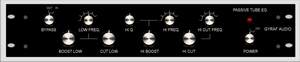
PE1A Front panel layout example
This is to give you an idea about how you can cram this eq into an 19"2U standard rack-case:
The PCB Layout
This is the long promised pcb layout for the diy-Pultec PE1A equalizer. This first PCB is for the passive equalizer, and the second is for the amplifier and power supply board. The filter pcb, carrying all the needed front panel switches and pots, is for convenience made as one 100x160mm pcb, as this size (eurocard) is a standard size of photoresist-pcb. You'll have to cut it thru' and connect the two pcb's with the five jumpers.
The amplifier/psu pcb is made as one 100x160mm pcb, carrying all the rest of the components, excluding the two power-transformers.
The pcb files are 600dpi gif files and PDF-files, and you will have to print them in some scale to get them to the needed exactly 100x160mm. If anyone has an idea of how this can be done more web-friendly, please don't hesitate to contact me..
The easiest way of doing the pcb's is to print it on a transparent or semi-transparent film on a laserprinter, and use this directly on the photoresist-pcb.
NOTE: The tracks side of the pcb is - as always - drawn MIRROR'ED to make closest contact between print and pcb. Think about this when doing the pcb's. When the text on the board reads the right way around seen from tracks side, then you're on right track.
While working on the prototype, I found that the gain in the originally intended ECC82 SRPP stage was too low. I thus changed to a different tube - the ECC88/6DJ8/6922 - which also provides lower output impedance and thus better low-frequency performance when driving the LL5402 output transformer. The changed tube means a different heater voltage - 6.3V - which is obtained by a LM317 voltage regulator.
The PCB layout and the Component placement for both the amplifier and the filter section (350 Kb pdf-file)
---------------------
Steffen has made a nice introduction to winding your own inductors for this kind of stuff. Check it out:
http://www.diygallery.de/DIYsites/inductor.html
Kev also has a page about making inductors:
http://recording.org/users/kev/Inductors.htm
The GroupDIY forum would be a good place to ask questions about this project...there's a good chance you will find me hanging around there...:
http://www.groupdiy.com/
Here's a link to the original Pultec EQP1A manual (PDF file):
Purple Audio's original schematic for the amplifier section.
ERRATA
If problems arises, errata and changes will be posted on this page.
03-03-2006: Note that the PCB silkscreen says "10K Lin" at the low-boost potentiometer - this should be 10K Log, like it's shown in the schematic.
Jakob Erland
03-03-2006
REVISION HISTORY:
11-2001: Amplifier changed to ECC88-tube for more gain and lower output impedance.
02-2002:1K Ohm resistor at sw3b changed to 10K Ohms - this fixes gain-loss when bypassing.
09-2002: PCB Artwork collected into one PDF-file for scaling reasons, gy_pd.pdf
Shown:
09-2002
HOME
