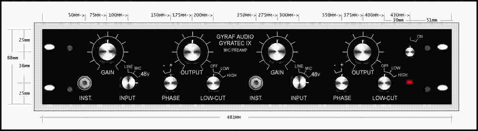
The G-IX front panel.
Updated 22 Dec 2004.
G9 Tube Mic-pre
The G-IX front
panel.
![]()
Project origins
For Group DIY this project started mid 2002,
perhaps September. An e-mail from Jakob that read,
"… - right now I'm
finishing the artwork for the DIY version of the GY9 dual
line/instrument/microphone preamplifier. "
OK so that got my
attention.
" It has a choice between OEP and Lundahl input and output
transformers on the same pcb, making it easier to DIY'ers."
Even ![]() better !!
better !!
Kev does tend to get
exceited when transformers and DIY are mentioned in the same sentence.
At
This stage he didn't even know that tubes were also to be part of the
project.
It turns out that this is really just a slight adaptation of the Gyratec IX, with wider choice of components. A couple of changes include changing the instrument input jack on the front panel to the "switching" type, so the input selection switch can be reduced to 3-position, and the omission of one relay.
You can find a review by
George Shilling of the of the Gyratec-2 Channel Strip.
There is some
similarity in the pre-amp of this Gyratec to the G9.
Review of
Gyratec II from "Resolution Magazine" jan. 2003.

The Revox G38 is the
inspiration behind our G-IX Tube Mic-pre
Having said that it should be noted that this is a big project and perhaps not a project to take on as a first project for a beginner. Jakob describes this as "......by far the most extensive DIY-project I have made so far. " The circuit boards are big, one is 15x20cm (=½ 20x30) and one is 10x15cm. One of these need to be further cut down to make the two front panel switch boards and this is not easy. I use a coping saw and trashed a few blades getting the job done. With an attempt is to cram all this into a little 2RU box, and with high voltages distributed around the PCB's, an board PSU, and quite a lot of interconnection, a true expert of the DIY world is going to be need to shake this one down.
'ta-dah' ,
Who should
step forward to take on this task but the 'dynamic duo' of
Byron and Kev. Two lambs to the slaughter. We have acted as test pilots to build
and review this project, so it can be described and be modified if there's
problematic areas DIY-wise - prior to publishing...
We think we are
there. Changes were made but to be honest, it was minimal and centered around
the way the power supply. The changes were done to keep the parts simple and
easily to obtained and hopefully this will mean, cheaper.
![]()
Lets get to some specifics
All details can be found at Gyraf Audio. You go here to check for any amendments and for all details. These words are meant as part review and part description and not a complete step by step how to construction guide.
Gyraf Audio's main page
http://www.gyraf.dk/
Please use the above link and work your way through the DIY section to find the latest news and changes to all the Gyraf DIY projects. Soon, there may be a single file that contains just the PCB's so Jakob can make changes and keep an amendments list on his site., So please do refer to Jakob's site for any amendments before you start etching.
![]()
"As you can see the G9 is really a
VERY simple, no-nonsense tube mic pre."
For a larger schematic, go to Jakob's
site
and remember to , right click and save as
As I stated above, even though development was well advanced by the time Byron and I started building some prototypes, there have been a couple of changes made in the area of the power supply and in particular the phantom power. This resulted in a daughter board to be fixed over the main PCB. You will not have to worry about this because by the time you download the artwork all the changes will have been made. We also had a rethink of the power transformer and have made things simple by using two easily obtained torriods 'back to back' to provide the voltages we need.
![]()
Built on a PCB for ease of DIY
The board overlay shows all component positions and connection points. To see the small details you will probably have to download Jakob's larger file as the one below is the smaller more compressed version. However if you look closely you might see that the G9 has four PCBs. One large main PCB with the bulk of the components including the audio transformers and two switch boards . The fourth PCB is in fact a power supply regulator board that you can use on your next tube prototype project. Jakob doesn't like to waste the magic copper board. You can also see the Farnell and Lundahl option for both input and output Audio Transformers.
 _
_ 
Here we can see some of the circuit boards that make up the G9 prototype that Byron and I had to work with. The small PCB above is the daughter board for phantom power. You will not have to use this as it will now be part of the main PCB. The larger L shaped PCB above is one of the two switch boards that contain the controls. If you have made an SSL clone or Pultec EQ, you will be familiar with both the style that Jakob uses and the Lorlin switches.
 _
_
Above is the large main
PCB and the small phantom daughter board and it's relative position. I have used
the Farnell Transformer option for both input and output. Most of the components
came from my local electronics enthusiast shop and apart from correct value and
sensible sizing to suit the PCB, I didn't go to any trouble by choosing esoteric
parts. I purchased the tubes from RS Components, a major electronics supplier,
and probably paid too much. The tubes were labeled National Electronics and were
also labeled, 'Made in China'. I have since found a couple of supplier that
could have supplied at half the price and given me a choice of manufacturer. So
take you time to track down your tubes of choice.
![]()
Project options and variations
I have grabbed a couple
of pictures from Jakob's site, (sshh - don't tell him). The one on the left
shows the original power supply set up with the single large 'normal' power
transformer. The picture on the right show a couple of things of interest. The
output audio TX's don't have the Shielding Cans and the most of the capacitors
are of the MKT - polly variety. I did use the shielding Cans on my output TX's
and my capacitors are mostly of the 'green cap ' variety. That's all I could get
at the time. Another difference is Jakob used ceramic tube sockets and I used
the plain old phenolic sockets. Again, all I could get at the time. The circuit
is reasonably forgiving but will probably respond well to the small touches to
improve things. A combination of the two would probably yield the best results.
Ceramic tube sockets, MKT caps or something more esoteric, Shielding cans on all
TX's and the new torriod power supply will likely make this a very good sounding
and well behaved Mic-pre. Of course the choice of tubes is likely to have it's
own effect on the results. However I am sure this project is going to impress
even if you don't get carried away with component choices and just use regular
'off the shelf' components.
 _
_
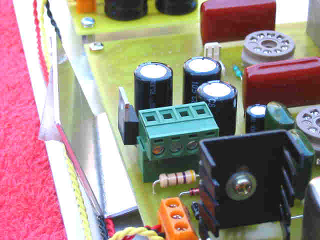
The picture on the left shows a metal plate that seems to be shielding the switch board of the second channel. I must remember to ask Jakob about this? Perhaps this was necessary with the old power supply.
 _
_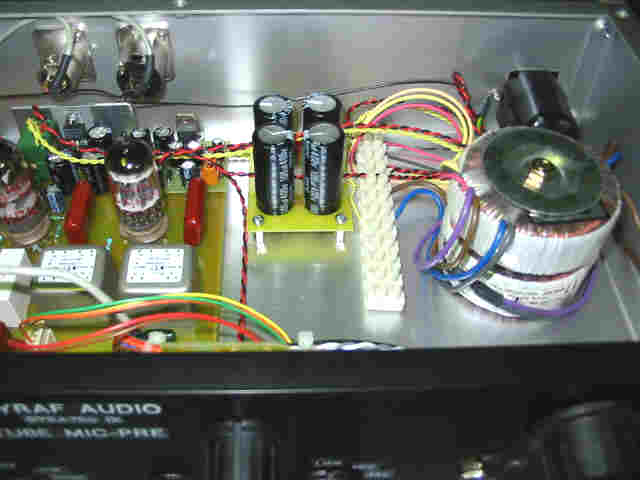
The picture on the left shows the bulk of the wiring to and from the main board. I have found that I have an oscillation at the highest gain setting. It seems to be related to the red (pin 2) wire at the gain connector. Perhaps a shielded wire will make it more stable. At the moment I have it separate from the orange (pin 3) wire. The second picture shows the power TX wiring. I am still to find a method that satisfies me. At the moment it is a screw terminal block. I haven't cut it as it will not stay. My current thinking is to extend the small PCB that has the larger electrolytic caps and add a row of screw terminals. This should be a convenient and neat connection point for the AC power wires.
 _
_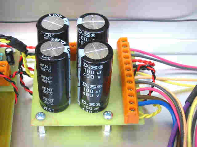
I have made the new PCB for the external caps and also added the screw terminals. This is better but not quite as good as I had hoped. It does provide a convenient and neat place to terminate the the transformers wires. As the PCB wasn't long enough to have a screw terminal per single wire I think on the next G9, I may use an extra two caps for smoothing and make the PCB long enough to accommodate more screw terminals. In case you hadn't already guessed, there is track work under the screw terminals to group pairs together.
_
If you look closely at the back panel you may see a lone black wire. This is the only connection from the bult of the circuit to chassis. The earth fromt the IEC inlet wraps round on a green/yellow wire straight to the mounting screw or rivet. The black wire is connected to this point and goes to pin 1 of both female XL3's. If you look closely at Jakob's schematic you will find this is clearly marked.
I think I can now screw the lid on and send it out on it's first recording session and get started on the next G9 which will be even better.
Too the best of my knowledge I have built this as per Jakob's plan. My only changes are the double electrolytic caps on the small PCB ( perhaps the next will get triple caps ) and a different power switch. I used a single pole push button switch and just switched the active. Jakob's plan shows on of the Lorlin rotary switches and he switched both active and neutral.
![]()
 _
_
A pair of regulators and some knobs from my local store. One regulator has an 'of the shelf heat-sink' and the second has a fabricated L shaped piece of aluminum that will carry the heat down to the base plate.

The above picture shows all boards. Note the main board is still missing the phantom power daughter board.
![]()
Parts, lists and general help
Parts, lists and general help
I've had a little to say about component choices or trouble shooting. This project will work and will probably impress even with simple component choices you may find at your local electronics hobby store. The project is open for improvements with more exotic components choices and it is is probably a good idea to check the G9 Meta thread at the LAB for the lastest parts and mod ideas. You may also find complete parts list applicable to many countries.
META - G9 Tube Micpre
http://www.prodigy-pro.com/forum/viewtopic.php?p=42650
Also at the lab you should find all
the trouble shooting help you need
http://www.prodigy-pro.com/forum/index.php
or
http://www.groupdiy.com/
![]()
Comments and impressions
Here is a very edited version of some of the comments that Byron made during the testing of the G9 :
A good project for anyone
DIY'er with limited knowledge and skills ( like me!! ). I am very happy
with this project.
I tried the G9 out with a variety of tubes and using different settings on the gain switch you can produce very useable tones. The G9 holds up against my favorite Jensen Mic-pre ( a DIY project from the Jensen site ). Given the very subjective nature of tube gear and the limited range of electric guitar, there is no 'winner'. The G9 provides the ability to audition different tones from a static signal, with each step in the gain you can hear the tone being affected. This is really cool for when we are too lazy to go back out and move a mic. It demonstrates the warm and non linear effect of the tube. Set the gain high and you can hear the signal brake up, then reduce it just enough, and keep that full sound I like so much. I also tried the Royer Mic ( yet another DIY project, this time from Tape-Op ) and it suited the G9, guitars have a big chunky sound which I really like. Not one for testing gear in isolation, I figure it has to fit into my 'system' and I have to like it on stuff I need it for. No sense jangling keys and I don't play keyboards. A Les Paul guitar with a Marshall combo amp, an SM57 with various mic placements into the G9 Mic-pre, then on to an LA2 ( you guessed it - DIY ) and into the DAW LA2, and then into the DAW made for a very cool signal path and a very enjoyable session.
My Jensen Mic-pre does sound good on just about anything so if the G9 wasn't as good as the Jensen I would have heard it immediately. The G9 is every bit as good. It is very subjective as to which is better. So even though my tests aren't technically based but user based, I can't imagine anyone doing rock music not having a lot of uses for this pre. The G9 does rock and is a real winner. Now I want to build one with Lundahl transformers.
Jakob has designed a very slick
project, why he isn't marketing this commercially is anyone's guess. ( He
has, see the Gyratec IX - Kev )
![]()
We just love those 'glow in the dark' glass thingys.
![]()
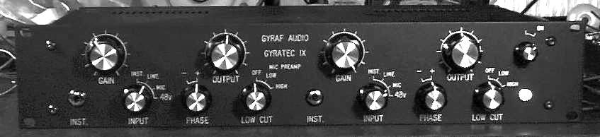
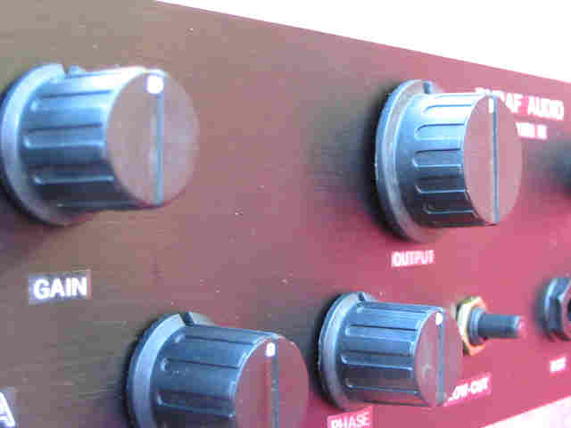
A front on view of Jakob's prototype.
![]()
![]()
Brought to you by Kev, Byron
and of course Jakob.